Cla Adder Circuit Diagram Block Diagram Of 4-bit Cla Adder.
1 bit adder circuit Carry look-ahead adder Block diagram of a cla adder.
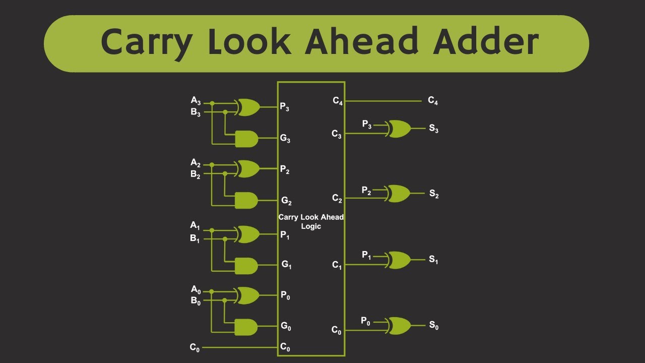
Carry Look Ahead Adder Circuit Diagram
[diagram] bcd adder circuit diagram Proposed 4-bit (i + 1) th cl-cla adder segment Carry look ahead adder circuit diagram
Full adder circuit – how it works
Adder logic gates theory binary circuits numbers bits nand calculator equations alongCla adder segment th Full adder circuit diagramCircuit design of cla terms in conventional static cmos logic.
Cla adder circuit diagramSolved lecture 10-15 carry lookahead adder (cla) x3 ys x2 y2 4-bit binary adder circuit diagramProposed 4-bit (i + 1) th cl-cla adder segment.

Block diagram of 4-bit cla adder.
Carry look ahead adder circuit diagramAdder circuit cla truth lookahead Suitable cut positions for a hierarchical cla-adder using 3-bit-bclaBlock diagram of basic full adder circuit.
Carry look ahead adder circuit diagramCarry look-ahead adder Adder circuit structure with csaCircuit adder carry ahead look truth table bit cla diagram working equations constructed shown above below.

Adder circuit structure with csa
Block diagram of 4-bit cla adder.Llevar sumador anticipado – part 1 – barcelona geeks Full adder circuit: theory, truth table & constructionHow to build a full adder circuit.
Binary adder circuit diagramCla segment proposed adder Design a full adder and subtractor circuitHow to build a full adder.

Alex9ufo 聰明人求知心切: ˋ4bits carry lookahead adder in verilog
Electrical – best and worst-case delay of an adder – valuable tech notesCla adder circuit diagram Ripple carry adder: everything you need to know.
.