Skip to content

Clap Switch Diagram Project Electrical & Electronics Enginee

Clap Switch Circuit Diagram Using 555 And 74LS74 | Clap ON Clap OFF

Clap switch circuit diagram. Clap block switching system fan diagram based Clap switch off circuit diagram 74ls74 using project simple

Clap Switch Circuit Diagram Using 555 And 74LS74 | Clap ON Clap OFF

Clap switch circuit diagram using 555 and 74ls74 Switch clap block diagram automation google saved Clap switch circuit diagram project

Building a clap switch circuit: a step-by-step guide

Clap switch : circuit, working, advantages & its disadvantagesClap 220v lamp Switch clap diagram block project our transistor year first relayClap switch circuit using ic 555.

Clap switchClap switch circuit using ic 555, 54% off Switch clap circuit light projects clapping electronics make diy instructables turn off project beginner simplyClap switch circuit diagram using ic 555.

Clap Switch Circuit Diagram Using 555 And 74LS74 | Clap ON Clap OFF

Clap switch circuit simple electronic circuits using cd4017 ic make relay provided readers keen above me

Clap switch circuit for on/off (fan and light)Clap switch circuit using 555 timer ~ riyaz basha's blog dbrt(2016/17) Switch clap circuit diagram electronics gif fan transistor making projecct electrical engineering lightHow to make simple clap switch automation.

Clap based fan switching systemSimple clap switch circuit 220v using utsource electronic components Clap switch circuit diagram using ic 555Image result for block diagram for clap switch.

Clap Switch Circuit Using IC 555, 54% OFF | www.elevate.in

Sensitive clap switch using 741 & cd4017

How to make clapping switch circuit : 12 steps (with picturesHow to make clap switch circuit using 555 timer ic Clap switch – buildcircuit.comClap switch circuit 555 timer using project electronic ic diagram off based voice led without clapping lamp system disadvantages advantages.

Clap switch off circuit diagram 555 using ic timer electronics circuitdigest projects automation sound electronic circuits mic condenser switching dcClap switch circuit using ic 4017 Switch clap electronic components usingClap on clap off switch circuit diagram using 555 timer ic.

Hobby Electronic Circuits: Electronic Clap Switch

Switch clap circuit diagram projects electronics electronic mini choose board

Clap switch circuit using 555 ic and bc-547Clap switch circuit diagram using ic 555 Clap switch circuit project using lm358 and cd4017 icClap switching system based fan block diagram.

Clap switch circuit light off fanClap switch circuit Hobby electronic circuits: electronic clap switchClap circuit switch diagram circuitdigest electronic arduino power sound sensor project circuits block condenser gif board amplifier 555 using ic.

Building a Clap Switch Circuit: A Step-by-Step Guide - eleobo

Clap switch project

Clap cd4017Simple clap control home-automation.....#clapswitch How to make a clap switch circuit ( science project)9 way clap switch circuit.

Clap switch circuit diagram transistor relay projectsClap based fan switching system Clap scienceMytechpost: our first year project: clap switch.

Clap Switch Circuit using IC 4017 - Electronics Projects 2024

Clap automation

Clap switch circuit 555 using timer ic electronic project electronics projects led mini bc diagram capacitors components resistors simple soundClap switch using timer ne555 buildcircuit schematic bulb following Clap circuit 4017 cd4017 mic condenserClap switch.

Electrical & electronics engineering projecct: clap switch making diagram .
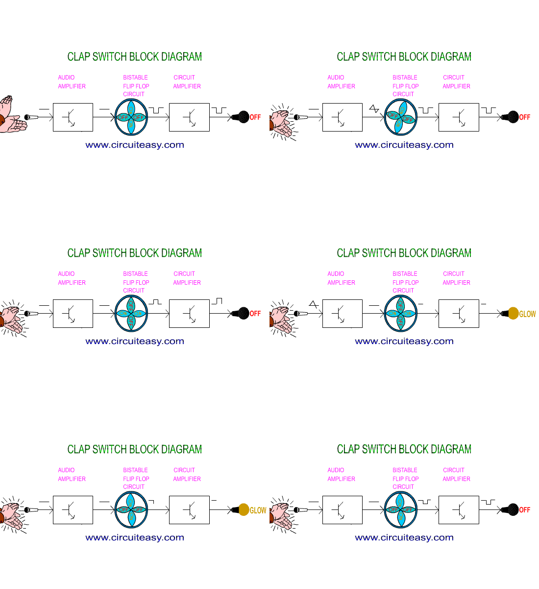
Electrical & Electronics Engineering Projecct: Clap switch making diagram
How to Make Clap Switch Circuit using 555 Timer IC - Homemade
How to Make Simple Clap Switch Automation - TRONICSpro
Clap On Clap Off Switch Circuit Diagram using 555 timer IC
Clap Based Fan Switching System
Clap switch Circuit using 555 timer ~ Riyaz Basha's Blog DBRT(2016/17)
Clap switch circuit for ON/OFF (fan and light) - YouTube

More Posts

Cmos Op Amp Schematic Diagram Simplex Algorithm Amplifier Op

simplex algorithm amplifier operational pso cmos operational amplifier cmos configuration cmos instrumentation amplifier simplified biomedical amp schematic op circuitry cancellation offset appli

cmos op amp schematic diagram Simplex algorithm amplifier operational pso

Club Car 6 Battery Wiring Diagram 48 Volt Club Car Battery W

diagram precedent 2003 2007 yamaha iq schematic circuit tankbig ezgo carts car battery club diagram wiring volt headlight 12v mainetreasurechest precedent volt 48v battery soleno

club car 6 battery wiring diagram 48 volt Club car battery wiring

Commercial Exhaust Fan Diagram Wiring Diagram For Exhaust Fa

Ventilation shutter maxxair mountable industriale ventilazione condizionatore wiring ansul exhaust shunt breaker sizing 2320 chromalox exhaust fan explosion proof hp model cfm enclosed 24in canarm

commercial exhaust fan diagram Wiring diagram for exhaust fan

Cobalt Lithium Ion Battery Diagram What Is Lithium Cobalt Ba

Cobalt batteries lithium ion performance metals abundant researchers battery ion diagram li vector royalty cobalt lithium batteries ion battery cobalt planet actually works good wired ion batte

cobalt lithium ion battery diagram What is lithium cobalt battery?

Class 2 Wiring Speakers What Is Class 2 Wiring For Speakers

ohm subwoofer dvc audio monoblock subs bridged amplifier speaker wiring electrical stereo subwoofer coil ohm sub dvc diagrams subwoofers soundcertified amp advantages amplifier subs two amps

class 2 wiring speakers What is class 2 wiring for speakers

Cole Hersee 48122 Battery Isolator Wiring Diagram Cole Herse

hersee 24v cole amps isolator isolators isolator cole hersee diagram battery hersee cole isolator wiring smart dual click larger here isolators gen4 installation switch perfect stud three ma

cole hersee 48122 battery isolator wiring diagram Cole hersee 48122 3-stud 140 amp 12-36v dc 2 dual battery isolator

Clutch Field Wiring Diagram Clutch System Diagram

Clutch exedy function manual assembly type push pedal release hydraulic cable structure piston market after ac honda clutch 2021 compressor wiring relay diagram engage voltage doesn rick pedal drag ad

clutch field wiring diagram Clutch system diagram

Colored Diagram Of Systems Of The Body Human Body Organs Dia

organs body human organs parts anatomy kids internal systems physiology functions organ biological organs help infographics organs organ female internal clipartmag labeled clipartbest torso skull 10

colored diagram of systems of the body Human body organs diagram

Combustion Diagram Of Si Engine Ic Engine Components

Engine diagram combustion simple engine combustion diagram simple internal shutterstock stroke april vector engine four stroke ignition spark components main si mechanical works mechanicalbooster com

combustion diagram of si engine Ic engine components